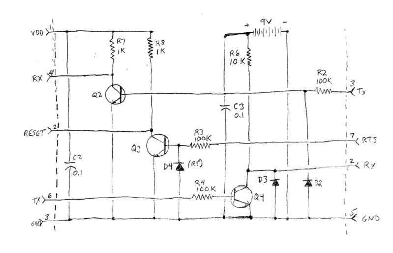
Sorry about the schematic, I don't know how to use drawing programs, so I just scanned my freehand sketch which was done in pencil.
FYI, transistors are 2N4401, diodes are 1N914.
Summary of static tests: I can switch the collector current off on the appropriate transistor by applying the correct voltage to JP1-6 (3V), DB-9 3 or 7 (9V) with the relevant side of the interface powered.
Software test results:
Connected the interface to a Comcast URC-1067ABG1. Ran debugtest.bat. Remote LED flashed twice, software reported "no response" -- I expected "Original JP1.2 found." Disconnected the remote from the interface, and noted two more flashes in rapid succession, obviously a reset. Remote works fine.
Couldn't think of a way to test the Rx leg (Q4 circuit) but I left the interface hooked up to the computer and inserted a 3V LED in JP1-3 & -4. Applied +3V (from a battery pack) to JP1-1, ground to JP1-3. The LED came on. Opened CommSniffer, opened the port and the LED came on. Applied a break signal. The LED went off for a split second then back on. Couldn't find a way to do something similar with RTS -- maybe it's there but I missed it.
Ran debugtest.bat again, was gratified to see the LED flash on then back off several times while it ran.
That's about it as far as symptoms. It's obvious there's something wrong with this circuit. Questions that come to mind (roughly in order of my suspicion):
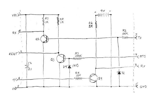
Value of R4
No diode from Q4 base to ground
No capacitor in parallel with R6
Value of R6
Other?
Before I start removing, replacing and re-soldering components, I would appreciate evaluations and suggestions. TIA--
Dave