Dear All,
A lovely forum and a lovely community and tools.
About 2 months ago our One4All remote started to malfunction (power button sends code in different protocol only in SAT mode all other buttons still work). After searching I found out about JP1 and saw the remote had holes in the battery compartment. I fitted pins and built a transistor serial JP1.2/3 interface.
I could not get it to work and started looking for a new JP1 remote.
I found one last week and it had JP1 pins and I used the codes in the manual to set up 3 of our devices (SAT, VCR, TV) and scanned for the last device (DVD). However ther is no 'info' or 'exit' button on the remote and they are not mapped anywhere else so I want to use the JP1 facility to move the missing functions onto the coloured buttons if possibe.
My old remote is a -----
URC 11-7940 R00 (label in battery compartment) URC 11-7950 R00, NOV 24, 2006 (on PCB)
3 volts, 4 device buttons (and one more unexposed button inside that seems to change device modes) JP1 labelled and numbered holes
New remote is -----
URC 11-2981 R00 (label in battery compartment) (cannot open)
3 volt, 8 device buttons, 6 pins, pin one numbered
I have tested as much as I can think of x
I am using XP professional SP3 Lenovo Intel Centrino (32 bit?)
I am using a reliable USB to serial converter (COM2) from MCT Corp with driver date 12/05/2004 ver 2.98.826.2 Edit: this unit does not support break signalling.
My transistor (2N2222) interface passes the Comtest v1.00 resistors and 9V loopback test and it causes both remotes to flash twice after dropping RTS
Debug_tester v0.03 causes both remotes to flash twice but reads 'Got no response' after all 3 reset attempts on COM2
jp1xtest v 0.00 causes both remotes to flash twice but returns '*** NO JP1.2/3 COMPATIBLE REMOTE FOUND! ***'
Remotes continue to operate when plugged into interface
Same symptoms for all tests with 5k6 or 105k6 resistor on JP1 pin 6
IR.exe v8.02 check interface (JP1.x) causes USB serial converter to flash lights, then remote flashes twice then returns message 'Failed to open JP1.x interface'
RMIR v2.02b download attempt on (JP1.x COM2) causes USB serial converter to flash lights then message 'No remotes found' and then remote flashes twice
I am at a bit of a loss as to where next I could look for inspiration
I have used 5k6 resistors for all but cannot see how this would matter.
I have not tried new batteries in the old remote but the new remote has only been used for a day with fresh Duracell's
Could both of these remotes be EEPROM devices?
Regards
Kalle
--
Johannesburg, South Africa
Starting out, JP1.x interface woes - what next
Moderator: Moderators
Starting out, JP1.x interface woes - what next
Last edited by KalleP on Mon May 14, 2012 9:30 am, edited 2 times in total.
Kalle Pihlajasaari
Lahti, Finland
Lahti, Finland
-
vickyg2003
- Site Admin
- Posts: 7109
- Joined: Sat Mar 20, 2004 12:19 pm
- Location: Florida
- Contact:
Re: Starting out, JP1.x interface woes - what next
Most remotes that only have the holes are JP1 not JP1.2/3 remotes and would be incompatible with the interface you built without an adapter.KalleP wrote:After searching I found out about JP1 and saw the remote had holes in the battery compartment. I fitted pins and built a transistor serial JP1.2/3 interface.
A signature blink back might be useful. See the Blink back instructions in the wiki.KalleP wrote:My old remote is a -----
URC 11-7940 R00 (label in battery compartment) URC 11-7950 R00, NOV 24, 2006 (on PCB)
3 volts, 4 device buttons (and one more unexposed button inside that seems to change device modes) JP1 labelled and numbered holes
New remote is -----
URC 11-2981 R00 (label in battery compartment) (cannot open)
3 volt, 8 device buttons, 6 pins, pin one numbered
Hi Vicky,
The PCB has the code URC 11-7950 R00 which leads me to believe it should be compatible with the URC7950 and this is listed as a JP1.3 in the spreadsheet.
It also looks like the URC 7930 and URC 7950 'Comfort Line' that are for sale on Amazon with the URC 7940. The PCB has some components missing which may be the 7950 learning circuit and it has the 5th device button inside.
The remotes also reset when the RTS signal is dropped which would lead me to think JP1.2/3 but here I may be totally wrong.
Found out about the blink codes after I posted and I get the following back, the URC 11-7940 codes match the URC 7940 and URC 7950 codes on the JP1 Lookup tool so I think it is the same remote.
URC 11-7940 R00
Signature 3029
SAT 0879
DVD 1345
VCR 0348
TV 0706
URC 11-2981 R00
Signature 3293
SAT 1959
DVD 1660
VCR 0348
TV 0706
Regards
--
Kalle Pihlajasaari
Johannesburg, South Africa
Kalle Pihlajasaari
Lahti, Finland
Lahti, Finland
I have a URC-7940. It does have the same electronics as the URC-7950 but one fewer device button, is JP1.3 and has holes. This agrees with KalleP's observations for his "old" remote.vickyg2003 wrote:Most remotes that only have the holes are JP1 not JP1.2/3 remotes and would be incompatible with the interface you built without an adapter.
Graham
-
vickyg2003
- Site Admin
- Posts: 7109
- Joined: Sat Mar 20, 2004 12:19 pm
- Location: Florida
- Contact:
And the signatures confirm they are JP1.3 as well. I haven't run into any JP1.x remotes without the pins, but I acknowledge that I'm not a hardware person. Now that I really think about it, a think the 15-100 didn't have pins either.mathdon wrote:I have a URC-7940. It does have the same electronics as the URC-7950 but one fewer device button, is JP1.3 and has holes. This agrees with KalleP's observations for his "old" remote.vickyg2003 wrote:Most remotes that only have the holes are JP1 not JP1.2/3 remotes and would be incompatible with the interface you built without an adapter.
-
Tommy Tyler
- Expert
- Posts: 411
- Joined: Sun Sep 21, 2003 11:48 am
- Location: Denver mountains
Hi Tommy,
Not sure of the file name as I printed the first PDF page out. It was two pages, one with transistors, one with an IC. The title says
BUILDING A SERIAL INTERFACE FOR JP1.2 and JP1.3 (FLASH) REMOTES
Tommy N. Tyler - Revised 10 February 2009
At the bottom of the page
CORRECTION DATED JUNE 26, 2009
about the 100k resistor
Heh, heh, just realised that it is your schematic, greetings to the guru.
I will try fresh batteries and reduce the resistors to 4k7 from the 5k6 if it seems like it might make a difference.
Regards
Kalle Pihlajasaari
Lahti, Finland
Lahti, Finland
-
Tommy Tyler
- Expert
- Posts: 411
- Joined: Sun Sep 21, 2003 11:48 am
- Location: Denver mountains
Hi Kalle,
Did you try a loopback test on the converter to make sure it is working? Tie pins 2 and 3 of the converter's DB9 connector together, and use whatever comm utility yoy used for the interface loopback test.You wrote:I am using a reliable USB to serial converter (COM2) from MCT Corp with driver date 12/05/2004 ver 2.98.826.2
Hi Tommy,
I was using the converter again 2 days ago to do testing on some other industrial automation systems successfully.
I did a quick pin 2-3 test now using ComTest and it works perfectly.
As mentioned in my first post the 9V JP1 interface loopback was also successful and I have checked the pinouts pretty carefully a few times.
I also looped the RTS output to the RXD input when doing the 9V test and correctly observed the RX light on the converter when turning the RTS on and off in ComTest.
Hardware wise everything seems good to go, most peculiar.
I have even tried to plugthe JP1 in backwards and it did not work. The remotes both get reset with all the software and the manual RTS toggle.
Should anything be sensitive to the 5k6 insteadof the 4k7. I will dig out some 22k resistor to parallel them if I must but an not expecting to find the problem there.
However I will be wiring up a 3.1V regulated supply and hooking it in when I have a free moment and trying to see if full supply might help, this is the only thing I can see that could be a electrical problem.
Is there any way I could manually try and send a simple "hello" command to the remote via ComTest at the preferred bit rate to see if the hardware responds? Can this be done via the keyboard or does it need control characters or other stuff?
Thanks for taking the time, I have been busy so had not done further tests since I started the thread but have been considering all the advice.
Kalle Pihlajasaari
Lahti, Finland
Lahti, Finland
-
Tommy Tyler
- Expert
- Posts: 411
- Joined: Sun Sep 21, 2003 11:48 am
- Location: Denver mountains
Hi Kalle,
If this is correct:
Using XP Pro SP3 and USB-to-Serial Converter with IR v8.02.
Original remote (URC 11-7940/7950) started to malfunction.
Installed 6-pin connector and built transistor flash interface.
Didn't work with original remote.
Bought new remote (URC 11-2981/URC 7950) with 6-pin connector.
Still didn't work. Resistors/batteries no help.
RESET signal is working OK, based on flashing LEDs.
Then my gut feel is that there is nothing wrong with the interface, and the problem must lie with the remote or the setup.
There's no way to send a "hello" to the remote, but we can verify that the remote "wants" to talk. Try THIS.
Hi Tommy and others,
I had a hour to relax with my laptop again and decided to see if the pin 5 wire might indeed have had something to do with the problem. I pulled it out even though it is only 2 inches long as the instructions are to cut it close. Still no change. I then downloaded realterm and started to proceed step by step through the identify procedured for manually communicating with the remote. It got to the place where it should go into the serial mode but each time it semed to be doing a normal reset with two blinks. This got me testing some more. The break condition was not being asserted so the proper sequence for serial mode was not being achieved.
Let this be a warning to all us people out there who have read this far. Not all USB to RS-232 converters are created equal. The units I have are well engineered with a good reputation when they were current but this failing has never been discovered. Using the break signal in the RS-232 specification on PCs is not really supported. To be honest I have never heard of it used as a control function, the name comes from the days when a break in a current loop Iteletype days) would be used to transfer of data and a longer than 11 bit break was a fault condition due to a break in the wire, it does not have the same symptom in the RS-232 world as a break in the wire leaves a floating data input in the markin (idle) state (except in some rare level shifters used in very early IBM equipment). The original PCs 8250 (16450) UART chips had a register to set the TX line into a break state for simulating a current loop wire break but as it was never really used obviously some USB converter developers have left it unimplemented.
I was reading the threads in the hardware problems section (where this might have better been placed in retrospect) and saw there was a recurring theme of interfaces that worked on a PC but not on a USB converter and many things were proposed. I think in many of these cases the problem will be in a bad USB converter chip design that will pass the handshake pin and data loopback tests correctly but is still unable to achieve the change to serial communications mode in the remote.
I will pop into the local computer shop and get an alternate USB converter and try it out and I expect all will work as advertised.
This possilility should be remembered in the documents and testing regiemes as a potential failure mode so this type of USB fault can be quickly weeded out. It can be simply tested on any serial port by connecting pin 3 to pin 1 (on a DE-9 connector) and monitoring the DCD control line input in realterm while setting the TXD pin to break condition (perhaps the 500ms flash feature can be easily detected).
I still have not tried the resistor or battery swap as the symptoms and sensitivity keep pushing them to the back of the likely queue. The short pin 5 wire might also have had no effect but I'm not going to put it back.
Thanks guys for all your suppport and for listening, I will try and send files of the new remotes memory dumps when I get it talking if they might be of some value.
Cheers
Kalle
--
Johannesburg, South Africa
Tommy Tyler wrote:Hi Kalle,
If this is correct:
Using XP Pro SP3 and USB-to-Serial Converter with IR v8.02.
Original remote (URC 11-7940/7950) started to malfunction.
Installed 6-pin connector and built transistor flash interface.
Didn't work with original remote.
Bought new remote (URC 11-2981/URC 7950) with 6-pin connector.
Still didn't work. Resistors/batteries no help.
RESET signal is working OK, based on flashing LEDs.
Then my gut feel is that there is nothing wrong with the interface, and the problem must lie with the remote or the setup.
There's no way to send a "hello" to the remote, but we can verify that the remote "wants" to talk. Try THIS.
Kalle Pihlajasaari
Lahti, Finland
Lahti, Finland
-
Tommy Tyler
- Expert
- Posts: 411
- Joined: Sun Sep 21, 2003 11:48 am
- Location: Denver mountains
-
Tommy Tyler
- Expert
- Posts: 411
- Joined: Sun Sep 21, 2003 11:48 am
- Location: Denver mountains
Kalle,
As I thought about it I realized I may be able to describe the idea well enough for you to understand and try it.
The very first serial interface I designed for flash remotes in March 2006 used two mechanical pushbutton switches for manually placing the remote into serial com mode. You could add these two switches to the interface you built and use the same method to initialize the remote if you can't find a USB-to-Serial converter that works, or don't want to spend a bunch of money to find out. It's a little more trouble, but it's reliable.
First, add a switch from the collector of Q1 to ground, and label it "START". That switch solves the problem with the break signal. Second, disconnect the RESET line from pin 2 of the remote connector to the collector of Q2, and instead route it through the second switch to ground. Label that switch "RESET".
Then when you want to upload or download your remote, press and hold START while momentarily pressing and releasing RESET. You'll notice the red LED does not double-blink, and the keyboard is inactive. Now you should be able to initiate an upload or download. Watch the screen for the double-blink of the little red simulated LED, then manually release the remote from com mode by momentarily pressing RESET alone. This time you will see a double-blink of the remote's LED.
If you want more details and a schematic, send me the e-mail address.
Tommy
Hi Tommy,
=====
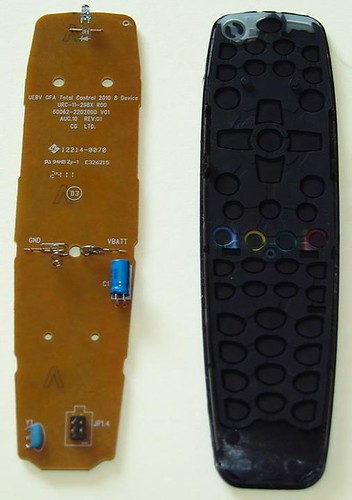
Update, I decided to force the new URC-2981 remote open, not too bad, start from the bottom, it says, would you believe it JP1.4 next to the connector the rest of the text as follows.
And I thought this US$12 remote was a good JP1.3 find.
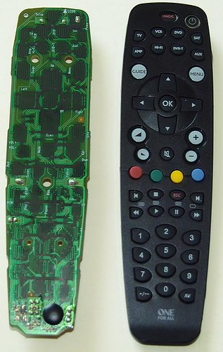
Here are a couple of pictures, I dunno how they will show up inline but here goes.
======
You can contact me on kp at ip.co.za if needed but the instructions were more than enough.
The plot thickens even more. I tried a slight modification to your instructions and managed to set my old remote into serial mode and received the following data back using realterm and a jumper to generate the break condition.
IS<J%V 30293029&
However the new remote will not go into serial data mode.
Could it be a JP1.4?
When measuring with reference to pin 3 in the remotes I measure on the old remote about 3V on 1, 2 and 6 and 0V on 4 and 5
on the new remote I get about 3V on pins 1, 2, 4, and 6, about 2.8V on pin 5
They seem rather different.
The new remote does not go into serial data mode and has the data in line pulled high but ignored.
Can I post this remote to you and you can play with it and see if it is any good, I am mildly piqued by the fact that the remote I got is perhaps a new protocol, I just want to watch How Its Made for crying in a bucket.
Thanks again for the personalised support, I am comforted.
Regards
Kalle
=====
Update, I decided to force the new URC-2981 remote open, not too bad, start from the bottom, it says, would you believe it JP1.4 next to the connector
and the fab dataUEBV OFA Total Control 2010 8 Devices
URC-11-298X R00
60062-2202000 V01
AUG.10 REV:01
CG LTD.
There is no provision for backlighting LEDs only one under the power button. There is a resistor capacitor thing between pins 2 and 3[logo] 12214-0070
[UL] 94HB Zy-1 E326215
[2411]
(D3)
And I thought this US$12 remote was a good JP1.3 find.
Here are a couple of pictures, I dunno how they will show up inline but here goes.
======
You can contact me on kp at ip.co.za if needed but the instructions were more than enough.
The plot thickens even more. I tried a slight modification to your instructions and managed to set my old remote into serial mode and received the following data back using realterm and a jumper to generate the break condition.
IS<J%V 30293029&
However the new remote will not go into serial data mode.
Could it be a JP1.4?
When measuring with reference to pin 3 in the remotes I measure on the old remote about 3V on 1, 2 and 6 and 0V on 4 and 5
on the new remote I get about 3V on pins 1, 2, 4, and 6, about 2.8V on pin 5
They seem rather different.
The new remote does not go into serial data mode and has the data in line pulled high but ignored.
Can I post this remote to you and you can play with it and see if it is any good, I am mildly piqued by the fact that the remote I got is perhaps a new protocol, I just want to watch How Its Made for crying in a bucket.
Thanks again for the personalised support, I am comforted.
Regards
Kalle
Tommy Tyler wrote:Kalle,
First, add a switch from the collector of Q1 to ground, and label it "START". That switch solves the problem with the break signal. Second, disconnect the RESET line from pin 2 of the remote connector to the collector of Q2, and instead route it through the second switch to ground. Label that switch "RESET".
Tommy
Kalle Pihlajasaari
Lahti, Finland
Lahti, Finland
Update on the older remote with my new USB to serial (TTL) converter.
My new USB to TLL converters arrived from China. They have a Silicon Labs CP2102 chip as opposed to the FTDI that is recommended and the MCT Corp ones I have that do not support the TXD BREAK signal. I had to connect the reset signal to the RTS line (this is connected to pin 24 of the tiny surface mount chip). These converters come in 3 typical flavours, one supports just TX and RX, the one I ordered has holes for the other modem control signals and there is one with pins for all the signals but this type is bigger. I added the extra pins to mine so I could use the wire harness to select the RTS signal for the remote reset. The TXD and RXD are incorrectly labelled compared to all other serial devices, the TXD is the input, this is a known bug in the labels on the device I got. I manually tested the inputs and outputs and they all work correctly (RI is not quite normal, it returns a pulse on every input change but we don't use it and it may just be an issue with RealTerm that may be displaying the RI change status bit).
I then connected the GND, RXD, TXD, RTS signals to my older JP1.3 remote and did the manual RealTerm test and received the
IS<J%V 30293029&
signatures back as before.
I ran the jp1xtest and Debug_Tester and both of them came back with positive results (see below).
I was getting hopeful and then tried with RM IR and set to Serial JP1.x on COM9 and tried to download, it generates a flash, short flash, double flash and then says
No RDF matches signature starting ****
or
No remotes found!
Raw download brings back 2k of '00'
IR causes a flash and then a double flash and returns
Failed to open JP1.x interface.
when trying the test interface option.
I must be having the worst luck with this interface issue. I may have to order an FTDI converter just to try and figure out what is going on. I have been keeping an eye out for a different One4All that might be an older JP1.3 design but there are rather limited options in the basic universals.
I will try out the JP1.4 remote when time and patience permits.
The debug programs returned the following good results.
and the other onejp1xtest version 0.00
*** FOUND A JP1.2/3 COMPATIBLE REMOTE ON COM9! ***
Signature is 30293029
Memory address is $0600
Memory size is $1000 (4096)
tester version 0.03
Parsing command list file tester.dat
Opening COM9
DCB paramaters:
DCBlength=28
BaudRate=38400
fBinary=1
fParity=0
fOutxCtsFlow=0
fOutxDsrFlow=0
fDtrControl=1
fDsrSensitivity=0
fTXContinueOnXoff=0
fOutX=0
fInX=0
fErrorChar=0
fNull=0
fRtsControl=1
fAbortOnError=0
fDummy2=0
wReserved=0
XonLim=32768
XoffLim=8192
ByteSize=8
Parity=0
StopBits=0
XonChar=17
XoffChar=19
ErrorChar=0
EofChar=0
EvtChar=0
wReserved1=0
CLRRTS
CLRDTR
SETDTR
SETBREAK
CLRBREAK
Purging RX and TX buffers
Reading up to 20 bytes to flush out spurious data
Didn't get any spurious data
Sending tEst command (45h)
Reading up to 20 bytes of response
Got no response
CLRDTR
SETDTR
SETRTS
CLRRTS
Purging RX and TX buffers
Reading up to 20 bytes to flush out spurious data
Didn't get any spurious data
Sending tEst command (45h)
Reading up to 20 bytes of response
Got no response
SETBREAK
SETRTS
CLRRTS
CLRBREAK
Purging RX and TX buffers
Reading up to 20 bytes to flush out spurious data
Didn't get any spurious data
Sending tEst command (45h)
Reading up to 20 bytes of response
Bytes read:
06
Original JP1.2 remote found!
CLRDTR
SETDTR
SETRTS
CLRRTS
Kalle Pihlajasaari
Lahti, Finland
Lahti, Finland