 |
JP1 Remotes
|
| View previous topic :: View next topic |
| Author |
Message |
DaveM59
Joined: 06 Apr 2008
Posts: 34
|
 Posted: Thu Jun 26, 2008 5:00 pm Post subject: Why doesn't this interface work? Posted: Thu Jun 26, 2008 5:00 pm Post subject: Why doesn't this interface work? |
 |
|
I read the history of the JP1.x serial interface designs and decided to have a go at making a simplified 1.2/1.3 interface that (I hoped) would work more reliably with laptops than the standard current design. Basically using a combination of brute force (a 9V battery) and old methodology (RTS line resets the remote). This is the result, and it's a failure, because even though my trial build passes all static tests, it fails tester.exe and the debugging version of same.
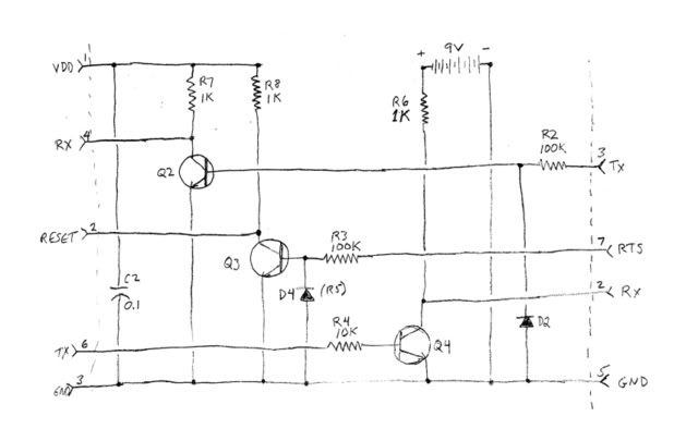
Sorry about the schematic, I don't know how to use drawing programs, so I just scanned my freehand sketch which was done in pencil.
FYI, transistors are 2N4401, diodes are 1N914.
Summary of static tests: I can switch the collector current off on the appropriate transistor by applying the correct voltage to JP1-6 (3V), DB-9 3 or 7 (9V) with the relevant side of the interface powered.
Software test results:
Connected the interface to a Comcast URC-1067ABG1. Ran debugtest.bat. Remote LED flashed twice, software reported "no response" -- I expected "Original JP1.2 found." Disconnected the remote from the interface, and noted two more flashes in rapid succession, obviously a reset. Remote works fine.
Couldn't think of a way to test the Rx leg (Q4 circuit) but I left the interface hooked up to the computer and inserted a 3V LED in JP1-3 & -4. Applied +3V (from a battery pack) to JP1-1, ground to JP1-3. The LED came on. Opened CommSniffer, opened the port and the LED came on. Applied a break signal. The LED went off for a split second then back on. Couldn't find a way to do something similar with RTS -- maybe it's there but I missed it.
Ran debugtest.bat again, was gratified to see the LED flash on then back off several times while it ran.
That's about it as far as symptoms. It's obvious there's something wrong with this circuit. Questions that come to mind (roughly in order of my suspicion):
Value of R4
No diode from Q4 base to ground
No capacitor in parallel with R6
Value of R6
Other?
Before I start removing, replacing and re-soldering components, I would appreciate evaluations and suggestions. TIA--
Dave
Last edited by DaveM59 on Thu Jun 26, 2008 7:03 pm; edited 1 time in total |
|
| Back to top |
|
 |
underquark
Expert
Joined: 20 Jun 2005
Posts: 874
Location: UK
|
| Posted: Thu Jun 26, 2008 6:49 pm Post subject: |
|
|
| Q3 should go via R3 to pin4 (DTR) on the DB9 not 7? |
|
| Back to top |
|
|
DaveM59
Joined: 06 Apr 2008
Posts: 34
|
| Posted: Thu Jun 26, 2008 7:16 pm Post subject: |
|
|
Thanks for the reply.
Maybe I am misunderstanding how the hardware works, but from Tommy Tyler's explanation of how JP1.2 is initialized, in this article:
http://www.hifi-remote.com/forums/dload.php?action=file&file_id=4259
It sounds like the standard routine used by the software is set up for the pulse circuit built into the standard serial interface. My idea was to eliminate this, so I resorted to using RTS to control the reset. This is possible because the software retains separate routine that does this, to maintain compatibility with the original JP1.2 interface. |
|
| Back to top |
|
|
DaveM59
Joined: 06 Apr 2008
Posts: 34
|
| Posted: Fri Jun 27, 2008 8:49 am Post subject: |
|
|
Okay, made a few changes, but no joy.
First, I added a diode between Q4 collector and ground. This was precautionary -- Tommy Tyler pointed out that some PCs like to put the Rx input voltage negative when the circuit is quiet. That is why he included the diode in his design.
Next, changed value of R4 to 100K. Then attached the 9V battery and ran a static test. Applying 3V to JP1-6 dropped the voltage at DB9-2 only from around 8.5 to 5 volts! So I did not bother to try a software test. I changed R6 out from 1K to 10K. This restored normal operation -- voltage on the static test swung from 8.5 down to zero again.
Unfortunately, same results from debugtest.bat: "got no response."
My next move will be to put a filter capacitor (0.1 microfarad) in the battery circuit, between the positive end and ground. After that I'll retest, but I don't expect it to help. If it does, I'll post the results.
I have pretty much given up on the idea of a diode across the base of Q4. Tommy does not have one in his circuit.
Anyway, that's about my last shot. If anyone has any other suggestions I would be grateful. |
|
| Back to top |
|
|
Thomas
Joined: 16 Feb 2008
Posts: 87
|
| Posted: Sat Jun 28, 2008 8:32 am Post subject: |
|
|
I breadboarded the JP1.x circuit [6/18/07 revision by Tommy Tyler] and it has worked perfectly.
I did omit Q1, R1, D1 as I had no interest in JP1.1 compatibility.
Your schematic does not quite match the design - some resistor values are different, using RTS rather than DTR, C1, D4, etc.
I would suggest you try Tommy's circuit on a breadboard first, verify it passes the tests, make and test modifications from there, and do the final build last.
_________________
Tom Carlson |
|
| Back to top |
|
|
DaveM59
Joined: 06 Apr 2008
Posts: 34
|
| Posted: Sat Jun 28, 2008 7:28 pm Post subject: |
|
|
Thanks for the reply, Tom. I may well end up doing what you suggest, however, for me this is more of a project that I got interested in because I saw that a number of people were having trouble making the standard design work, particularly on laptops. I have one of Tommy's USB interfaces that I use for downloading and programming JP1.2/3 remotes, so I don't need to get this one operational as quickly as possible.
Anyway, I have addressed a number of your concerns in the latest modifications. Here is a schematic of my project as currently constituted:
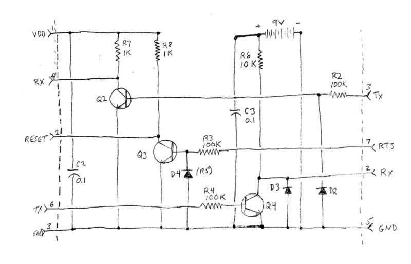
I went through some interesting sideroads along the way, which I won't bother to chronicle, but I will say that this interface, like the first iteration posted above, passes all static tests. All three circuits work as they should, current on the "output end" of each one can be switched on and off by applying appropriate voltage to the "input end."
Unfortunately, the unit still fails debugtest.bat with a "Got no response" message. During the test, the remote LED flashes once. Does not flash twice at the end, does not flash twice when the interface is unplugged and is inoperable. (Easily reset by removing one battery for a few seconds and replacing, of course.)
Using Simpleterm (akin to CommSniffer) I can put the remote into serial mode by setting break (taking pin 4 low), then setting and clearing RTS (reset pin 2), and finally clearing break. If I disconnect the remote at this point, it behaves just like after debugtest -- no flashes and the remote is inoperable. I can then reconnect it, and put it back into normal mode by setting and clearing RTS.
I have verified all these results by repeating the tests on a second computer.
My conclusion: though they pass the static test, either the Rx circuit (Q2), or the Tx circuit (Q4), or possibly both, will not communicate at 38.4K bps. I am more inclined to suspect the Q4 circuit because I know that at least some signal is getting through Q2 to the remote, whereas nothing is getting from the remote to the computer.
I would appreciate any suggestions for further tests that might pin down the cause of the failure. |
|
| Back to top |
|
|
binky123
Expert
Joined: 14 Feb 2004
Posts: 1292
|
| Posted: Sun Jun 29, 2008 12:20 am Post subject: |
|
|
If you get one LED blink and then no response, I'm fairly certain you are in serial mode as you need a battery disconnect to reset the remote.
You may want to consider using your existing and working cable from Tommy and only use that for certain pins/circuits to isolate which works and doesn't work on your current design. First test your reset circuit with tommy's working cable and move to the TX and then the RX circuits. |
|
| Back to top |
|
|
DaveM59
Joined: 06 Apr 2008
Posts: 34
|
| Posted: Sun Jun 29, 2008 4:39 pm Post subject: |
|
|
Binky, I think I understand your suggestion. You are telling me to do loopback test using a crossover connection between the pins of the JP1 connectors on Tommy's USB interface and the pins of my project serial cable. Example: to test the Tx circuit of the project interface, 3 to 3 (Gnd-Gnd) and 4-6. Then open two copies of Commsniffer or Simpleterm, on one open Com 1 (The serial interface) and on the other Com 3 (Tommy's USB) and send a string of characters from Com 3 to Com 1.
Sounds like a plan, I'll let you know what happens --
Dave |
|
| Back to top |
|
|
binky123
Expert
Joined: 14 Feb 2004
Posts: 1292
|
| Posted: Sun Jun 29, 2008 7:37 pm Post subject: |
|
|
| What I'm saying is hook Tommy's cable up to remote and verify it works. Then disconnect the RESET circuit from tommy's cable and hook IDC-6 to your circuit and hook your circuit to DB9-7 RTS. You are still using Tommy's Rx and TX circuits but using your Reset circuit. If this is ok, then you know your RESET circuit is working. Next, proceed to disconnect Tommy's TX circuit and connect up your TX circuit. If this works(your RESET, TX and Tommy's RX circuit) then proceed to connecting your RX circuit. You can also do individual circuit tests by keeping Tommy's circuit for the other 2 circuits(e.g. Reset,TX) and testing your 3rd circuit(RX). |
|
| Back to top |
|
|
DaveM59
Joined: 06 Apr 2008
Posts: 34
|
| Posted: Mon Jun 30, 2008 5:36 am Post subject: |
|
|
Thanks for the clarification, Binky.
This will require building a special set of jumpers. May take some time. I'll let you know how it works out. |
|
| Back to top |
|
|
DaveM59
Joined: 06 Apr 2008
Posts: 34
|
| Posted: Mon Jun 30, 2008 8:55 am Post subject: |
|
|
Just a note to say thank you to everyone who helped with various suggestions. I now have a working interface. My design is OK, my execution was not.
The root cause of all the difficulties was wiring errors. Gradually I picked up on some clues that the loopback tests had been giving me and was able to correct them.
For those who wonder what the wiring errors were, I'll just point out that Tommy's original layout is based on the choice of a female DB9 connector. I used a male, and being dimensionally challenged, at first did not realize that this would require some other changes. It took a lot of hard staring at pinout diagrams to realize what all those changes were.
Anyone who is contemplating modifying their serial interface because they are having problems getting it to work with a notebook, I hope to publish soon step by step instructions on how to modify a standard JP1.2/1.3 serial interface to make this battery powered version.
Meanwhile, two notes for anyone who has been following this: number one, the modified schematic, as shown in my post of Sat. June 28 7:28PM, is definitely the one to follow. The higher resistor values in the Q4 circuit (R4 and R6) will give far longer battery life. Also, it is important to have a diode (D3) across the collector line in order to protect Q4 from possible negative spikes from the PC's serial port. |
|
| Back to top |
|
|
|
|
You cannot post new topics in this forum
You cannot reply to topics in this forum
You cannot edit your posts in this forum
You cannot delete your posts in this forum
You cannot vote in polls in this forum
|
Powered by phpBB © 2001, 2005 phpBB Group
|

