 |
JP1 Remotes
|
| View previous topic :: View next topic |
| Author |
Message |
vickyg2003
Site Admin
Joined: 20 Mar 2004
Posts: 7073
Location: Florida
|
 Posted: Fri Jun 16, 2017 8:22 pm Post subject: Very Basic Power supply questions. Posted: Fri Jun 16, 2017 8:22 pm Post subject: Very Basic Power supply questions. |
 |
|
1) I got an HDMI switch that is powered by USB, but no adapter came with it. The documentation says it needs a 5v 1.5 amp power supply. I have a Monster Power surge protetorp that has two USB ports. One is labeled phone the other labeled tablet. I can't find any documentation on these ports. Would one of these USB ports be safe to use with my switch?
2) I've got an old battery operated Pac-Man game that you plug into a TV. It takes 4 AA batteries. The batteries are always dead when we want to use it. How would I go about changing this to use an external power supply?
_________________
Remember to provide feedback to let us know how the problem was solved and share your upgrades.
Tip: When creating an upgrade, always include ALL functions from the oem remote, even if you never plan on assigning them to a button. Complete function lists makes an upgrade more helpful to others.
|
|
| Back to top |
|
 |
The Robman
Site Owner
Joined: 01 Aug 2003
Posts: 21254
Location: Chicago, IL
|
| Posted: Fri Jun 16, 2017 8:26 pm Post subject: |
|
|
1) You could try it and see. If the switch uses USB power and they didn't provide a power supply, I have to imagine that most regular USB power supplies would work (ie, the kind that you use with phones, etc).
2) 4 AA batteries give 6v, so all you need to do is find a 6v AC adapter and then rip off the plug at the end and solder the wires to the + and - battery terminals in the game.
_________________
Rob
www.hifi-remote.com
Please don't PM me with remote questions, post them in the forums so all the experts can help! |
|
| Back to top |
|
|
vickyg2003
Site Admin
Joined: 20 Mar 2004
Posts: 7073
Location: Florida
|
| Posted: Fri Jun 16, 2017 8:48 pm Post subject: |
|
|
| The Robman wrote: |
2) 4 AA batteries give 6v, so all you need to do is find a 6v AC adapter and then rip off the plug at the end and solder the wires to the + and - battery terminals in the game. |
I looked through my chargers, and I have one that says 5.8V 130mA. I cut the end off it. It didn't have wires like a lamp, where you can see two distinct wires, it looked like one wire. When I cut off the end one of the wires is sheathed in white plastic, the other one is bare. Can I use this? And if so which one is the -? And the wires are twisted around a fiber, is this going to be a problem with soldering?
Will this pose any danger? This is used by small children and saftey first!
_________________
Remember to provide feedback to let us know how the problem was solved and share your upgrades.
Tip: When creating an upgrade, always include ALL functions from the oem remote, even if you never plan on assigning them to a button. Complete function lists makes an upgrade more helpful to others.
|
|
| Back to top |
|
|
The Robman
Site Owner
Joined: 01 Aug 2003
Posts: 21254
Location: Chicago, IL
|
| Posted: Fri Jun 16, 2017 9:17 pm Post subject: |
|
|
Do you have a multimeter? If so, use that to test the wires to see which is + and which is -.
As for safety, I would drill a small hole in the battery door (or anywhere else that you think might work), just big enough for the wire to go through, then tie a knot in the end of the wire after it has been fed through so it can't be pulled back.
_________________
Rob
www.hifi-remote.com
Please don't PM me with remote questions, post them in the forums so all the experts can help! |
|
| Back to top |
|
|
vickyg2003
Site Admin
Joined: 20 Mar 2004
Posts: 7073
Location: Florida
|
| Posted: Fri Jun 16, 2017 9:56 pm Post subject: |
|
|
My DH has something that looks like a it might be a multimeter in the garage. I set it to 2v and tested a battery. I think my charger might be proprietary so I'm just going to get one that is generic and has 2 wires coming out. I'll get back to you on the where to solder when it arrives.
_________________
Remember to provide feedback to let us know how the problem was solved and share your upgrades.
Tip: When creating an upgrade, always include ALL functions from the oem remote, even if you never plan on assigning them to a button. Complete function lists makes an upgrade more helpful to others.
|
|
| Back to top |
|
|
vickyg2003
Site Admin
Joined: 20 Mar 2004
Posts: 7073
Location: Florida
|
| Posted: Fri Jun 16, 2017 10:06 pm Post subject: |
|
|
This looks cool.
http://www.wikihow.com/Make-Battery-Eliminators
_________________
Remember to provide feedback to let us know how the problem was solved and share your upgrades.
Tip: When creating an upgrade, always include ALL functions from the oem remote, even if you never plan on assigning them to a button. Complete function lists makes an upgrade more helpful to others.
|
|
| Back to top |
|
|
The Robman
Site Owner
Joined: 01 Aug 2003
Posts: 21254
Location: Chicago, IL
|
| Posted: Sat Jun 17, 2017 10:09 am Post subject: |
|
|
If you want to avoid modifying the Pacman game itself, that would be the way to go.
I had someone with a similar request here several years ago, it was a guy who wanted to use Timed Macros on a Producer 8 to switch something on the TV in his bar, so basically he wanted to leave the remote in one place forever and have it keep changing channels or something, so needless to say, he wanted to plug it in rather than have it use batteries, so I had him do the same thing, hack an AC adapter and solder the wires into place, which he did and it worked.
_________________
Rob
www.hifi-remote.com
Please don't PM me with remote questions, post them in the forums so all the experts can help! |
|
| Back to top |
|
|
The Robman
Site Owner
Joined: 01 Aug 2003
Posts: 21254
Location: Chicago, IL
|
| Posted: Sat Jun 17, 2017 10:15 am Post subject: |
|
|
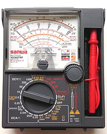
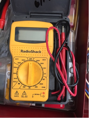
As for the multimeter, this is what a typical "analog" and "digital" multimeter look like, they let you switch between measuring resistance, AC voltage or DC voltage, and maybe capacitance:
_________________
Rob
www.hifi-remote.com
Please don't PM me with remote questions, post them in the forums so all the experts can help! |
|
| Back to top |
|
|
vickyg2003
Site Admin
Joined: 20 Mar 2004
Posts: 7073
Location: Florida
|
| Posted: Sat Jun 17, 2017 2:58 pm Post subject: |
|
|
This is the thing I found in the garage that I thought was a multimeter. No idea how to use this thing and electricity scares me.
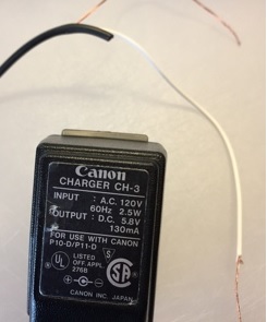
This is the charger that I cut the end off. There is a little diagram that probably tells me which one is positive and which is negative.
 |
|
| Back to top |
|
|
The Robman
Site Owner
Joined: 01 Aug 2003
Posts: 21254
Location: Chicago, IL
|
| Posted: Sat Jun 17, 2017 3:34 pm Post subject: |
|
|
If you turn the dial to about the 2 o'clock position, you will be in 20v DC range, then put the red lead on what you think is the positive wire and the black lead on the negative wire, and you should see 5 or 6 volts on the screen. If you get it backwards, you might see a negative number.
I've never used a digital multimeter, so I'm guessing about the screen readouts, with my analog meter, if I get it backwards, the needle tries to go below zero.
Don't let 6v electricity scare you, lol.
_________________
Rob
www.hifi-remote.com
Please don't PM me with remote questions, post them in the forums so all the experts can help! |
|
| Back to top |
|
|
pH7_jp1
Joined: 14 Sep 2003
Posts: 480
Location: Sterling Heights, MI
|
| Posted: Sat Jun 17, 2017 6:12 pm Post subject: |
|
|
| Yes, the little diagram is saying that the wire in the center is negative and that the outer sheath is positive. If you are lucky the switch will have a similar diagram that shows what it needs, so you know how to connect to the plug. |
|
| Back to top |
|
|
The Robman
Site Owner
Joined: 01 Aug 2003
Posts: 21254
Location: Chicago, IL
|
| Posted: Sat Jun 17, 2017 8:17 pm Post subject: |
|
|
The diagram actually describes how the original plug (ie, the one she removed) was configured (ie, it had a negative tip). I don't know if that means the wire was also configured that way. I have some adapters that have a plug in the middle of the wire which allows you to switch the tip between negative and positive.
_________________
Rob
www.hifi-remote.com
Please don't PM me with remote questions, post them in the forums so all the experts can help! |
|
| Back to top |
|
|
vickyg2003
Site Admin
Joined: 20 Mar 2004
Posts: 7073
Location: Florida
|
| Posted: Sun Jun 18, 2017 9:31 am Post subject: |
|
|
| The Robman wrote: |
Don't let 6v electricity scare you, lol. |
But its plugged into the wall!!! 
| Phil wrote: | | If you are lucky the switch will have a similar diagram that shows what it needs, so you know how to connect to the plug. |
Hadn't taken that into consideration. I have no practical knowledge on this, I was playing arcade games when I should have been taking apart electronics.  I guess the batteries complete the circuit the + of one end to the - at the other one, so I need to know which way this flows. So I need to figure out which + and which - to use in the battery compartment so I can complete the circuit without the batteries. I guess the batteries complete the circuit the + of one end to the - at the other one, so I need to know which way this flows. So I need to figure out which + and which - to use in the battery compartment so I can complete the circuit without the batteries.
This really does illustrate that I am not a hardware person. I'm into this hobby to keep the remote-clutter off the coffee table!
_________________
Remember to provide feedback to let us know how the problem was solved and share your upgrades.
Tip: When creating an upgrade, always include ALL functions from the oem remote, even if you never plan on assigning them to a button. Complete function lists makes an upgrade more helpful to others.
|
|
| Back to top |
|
|
The Robman
Site Owner
Joined: 01 Aug 2003
Posts: 21254
Location: Chicago, IL
|
| Posted: Sun Jun 18, 2017 10:25 am Post subject: |
|
|
I think Phil was getting your 2 separate requests mixed up. If I understand your original post correctly, you are trying to power 2 separate devices.
First you have a switch that uses a USB connection for power, so that one you can power with a regular USB cable and a power brick, so no need to worry about +/- polarity there.
Second, you have an old Pacman game that only runs on 4 AA batteries, and as each battery gives 1.5v, you're looking at a total of 6v approximately. The flat end of batteries is the negative end and the end with a little button shape is the positive end, or to put in terms of the terminals in the game, the end with the spring is the negative end and the flat end is positive. As there are 4 batteries, I assume you line them up in a 2*2 pattern, so one end will simply be a pass-thru connector, the other end will have separate connectors that actually carry the power into the device. That is the end where you would solder your wires.
And even though the AC adapter plugs into the wall, the power coming out of the wires is the same as what the 4 batteries would give you, so if you're not afraid to handle the batteries, don't worry too much about the adapter.
_________________
Rob
www.hifi-remote.com
Please don't PM me with remote questions, post them in the forums so all the experts can help! |
|
| Back to top |
|
|
vickyg2003
Site Admin
Joined: 20 Mar 2004
Posts: 7073
Location: Florida
|
| Posted: Sun Jun 18, 2017 11:53 am Post subject: |
|
|
| The Robman wrote: | | I think Phil was getting your 2 separate requests mixed up. If I understand your original post correctly, you are trying to power 2 separate devices. |
You do
| Quote: |
First you have a switch that uses a USB connection for power, so that one you can power with a regular USB cable and a power brick, so no need to worry about +/- polarity there. |
Yes, we decided since I don't have a USB power brick, I'd plug it into the USB slot labeled "phone" on my surge protector.
| Quote: |
Second, you have an old Pacman game that only runs on 4 AA batteries, and as each battery gives 1.5v, you're looking at a total of 6v approximately. The flat end of batteries is the negative end and the end with a little button shape is the positive end, or to put in terms of the terminals in the game, the end with the spring is the negative end and the flat end is positive. As there are 4 batteries, I assume you line them up in a 2*2 pattern, so one end will simply be a pass-thru connector, the other end will have separate connectors that actually carry the power into the device. That is the end where you would solder your wires. |
We are talking about doing this from the battery comartment and not tring to open the box, correct? I'm still a little fuzzy here, but I now think I can do it, if nothing else I can use the dowel method. That one I get. I've been looking at how other people put together there arcade games, looking for something that looks good. I did learn how to use power tools when they decided that the girls in our school would be required to take shop. I just wish they had been that open minded about letting the girls take physics instead of biology!
| Quote: |
And even though the AC adapter plugs into the wall, the power coming out of the wires is the same as what the 4 batteries would give you, so if you're not afraid to handle the batteries, don't worry too much about the adapter. |
Good to know as I was terrified of touching it with that multi-meter.
_________________
Remember to provide feedback to let us know how the problem was solved and share your upgrades.
Tip: When creating an upgrade, always include ALL functions from the oem remote, even if you never plan on assigning them to a button. Complete function lists makes an upgrade more helpful to others.
|
|
| Back to top |
|
|
|
|
You cannot post new topics in this forum
You cannot reply to topics in this forum
You cannot edit your posts in this forum
You cannot delete your posts in this forum
You cannot vote in polls in this forum
|
Powered by phpBB © 2001, 2005 phpBB Group
|

