| View previous topic :: View next topic |
| Author |
Message |
The Robman
Site Owner
Joined: 01 Aug 2003
Posts: 21254
Location: Chicago, IL
|
 Posted: Tue Aug 02, 2016 12:26 pm Post subject: can you convert a 220v device to use 110v? Posted: Tue Aug 02, 2016 12:26 pm Post subject: can you convert a 220v device to use 110v? |
 |
|
if so, any tutorials?
_________________
Rob
www.hifi-remote.com
Please don't PM me with remote questions, post them in the forums so all the experts can help! |
|
| Back to top |
|
 |
Barf
Expert
Joined: 24 Oct 2008
Posts: 1417
Location: Munich, Germany
|
| Posted: Tue Aug 02, 2016 1:15 pm Post subject: |
|
|
Replace the power supply. Search for 110 v power supplies on Ebay and in forums.
BTW, it is formally "230 V", at least here in Germany. |
|
| Back to top |
|
|
The Robman
Site Owner
Joined: 01 Aug 2003
Posts: 21254
Location: Chicago, IL
|
| Posted: Tue Aug 02, 2016 3:13 pm Post subject: |
|
|
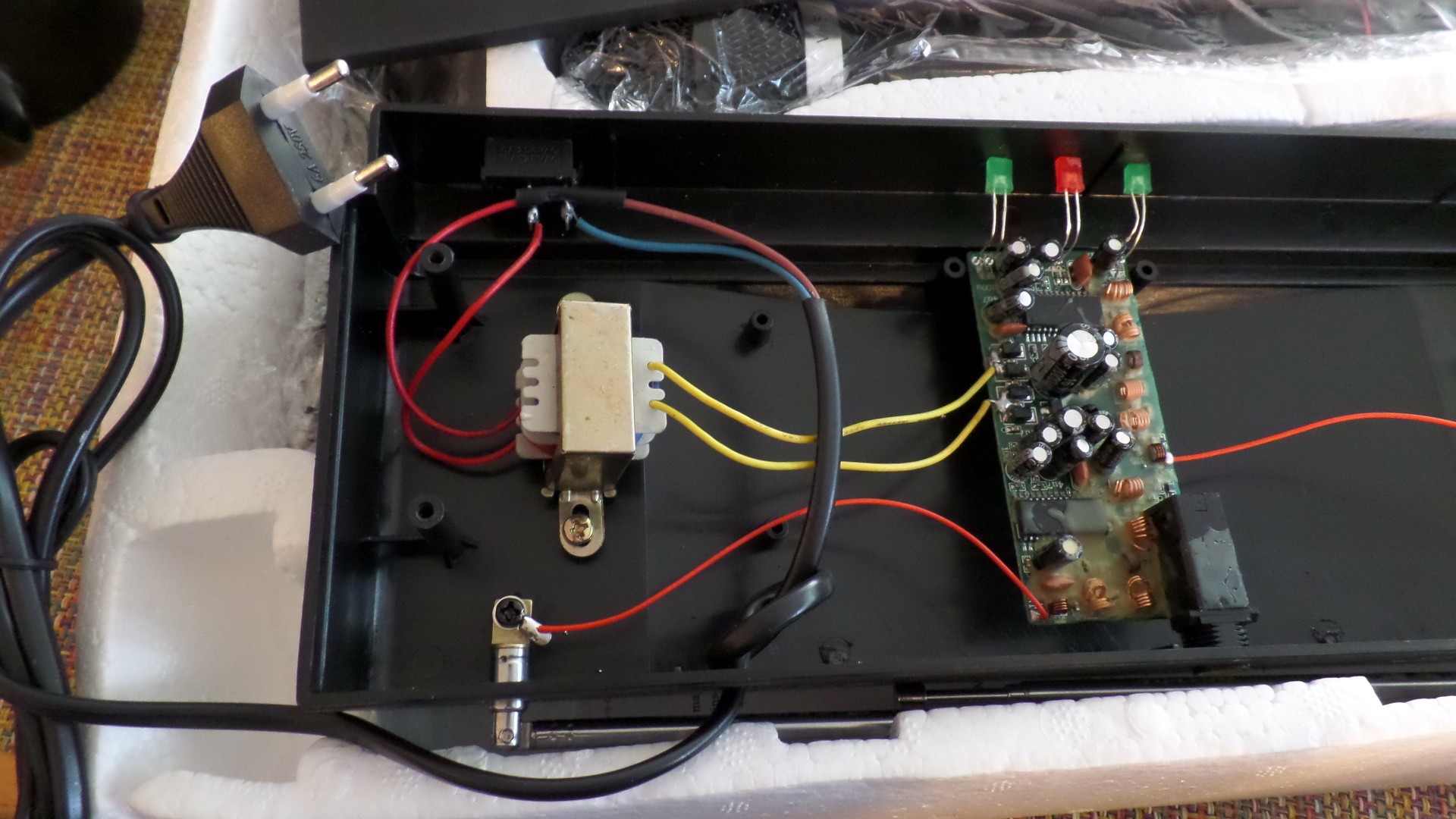
Yeah, and it's 240v in the UK, but the unit is actually labeled as 220v. It doesn't have an external power supply, which could be easily replaced, and looking inside, it doesn't have a separate power supply PCB.
Here's a look at the inside (click to enlarge)...
_________________
Rob
www.hifi-remote.com
Please don't PM me with remote questions, post them in the forums so all the experts can help! |
|
| Back to top |
|
|
yaworski
Joined: 22 Jun 2014
Posts: 454
Location: Warsaw, Poland
|
| Posted: Tue Aug 02, 2016 4:06 pm Post subject: |
|
|
You would need to replace a transformer to one that has lower turn ratio between primary and secondary coils. That's all that matters. You would need to know what is the output voltage on secondary coil of the transformer with nominal 220 V input and then replace it for one that gives exact or close output voltage with 110 V on primary coil.
You would need to desolder those 2 yellow wires from the PCB. I can see that they are soldered directly to the rectifier bridge built from 4 diodes so you need to be careful not to overhead them when desoldering. You could also just cut the wires somewhere between transformer and PCB and then just connect then to ones from new transformer (just use good electrical isolating tape or heatshrinking tubes to properly isolate the connections).
--edit--
If you have multimeter, you can check output voltage from the transformer by setting it to AC voltage (not DC, as this is still AC before going to the rectifier) and then probing voltage between yellow wires. The voltage on the secondary is probably something between 6 and 12 volts but you still need to be extra careful when working on open device connected to mains.
_________________
Marcin
Last edited by yaworski on Tue Aug 02, 2016 4:10 pm; edited 1 time in total |
|
| Back to top |
|
|
mdavej
Expert
Joined: 08 Oct 2003
Posts: 4505
|
| Posted: Tue Aug 02, 2016 4:06 pm Post subject: |
|
|
| If there are no markings on the transformer, you could cut the yellow wires, apply 110 at the input and measure the output. That will tell you how much it steps down. Then just replace it with a transformer that steps down half the amount of the original. The only kicker is 50 Hz vs. 60 Hz. Hopefully that won't have too much impact. Otherwise you'll have to replace some caps too. |
|
| Back to top |
|
|
yaworski
Joined: 22 Jun 2014
Posts: 454
Location: Warsaw, Poland
|
| Posted: Tue Aug 02, 2016 4:14 pm Post subject: |
|
|
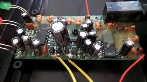
@mdavej: it won't have any impact. As you can see it's a simple rectifier bridge on the PCB and the main cap smoothing out the output is really big one (1000 uF?). 10 Hz difference is omittable :).
Also there seems to be a voltage regulator right next to the cap so the output voltage from the transformer doesn't need to be spot on. Would be nice to have a part number of the regulator to know what is its output voltage.
_________________
Marcin
Last edited by yaworski on Tue Aug 02, 2016 4:19 pm; edited 1 time in total |
|
| Back to top |
|
|
The Robman
Site Owner
Joined: 01 Aug 2003
Posts: 21254
Location: Chicago, IL
|
| Posted: Tue Aug 02, 2016 4:18 pm Post subject: |
|
|
Interesting idea to use 110v to see what voltage it outputs because I don't have a 220v supply to measure the output voltage the regular way.
Would it be too much to hope for that the desired output is 9v ? 
_________________
Rob
www.hifi-remote.com
Please don't PM me with remote questions, post them in the forums so all the experts can help! |
|
| Back to top |
|
|
yaworski
Joined: 22 Jun 2014
Posts: 454
Location: Warsaw, Poland
|
| Posted: Tue Aug 02, 2016 4:22 pm Post subject: |
|
|
Rob, I've edited my previous post. As you can see there's a voltage regulator on the PCB (right next to the big cap, it has 3 "legs").
The voltage doesn't need to be spot on to what is required because the regulator should be able to bring it down to required one as long as the difference isn't too much (it doesn't have a heat sink). If you could try to read the part number on the regulator that would tell us what is the output voltage from the regulator itself.
_________________
Marcin |
|
| Back to top |
|
|
yaworski
Joined: 22 Jun 2014
Posts: 454
Location: Warsaw, Poland
|
| Posted: Tue Aug 02, 2016 4:38 pm Post subject: |
|
|
I've been able to read the part number from the second photo. It's LM78L05 5 volts positive voltage regulator. According to the datasheet its maximum voltage input is 30 volts. I think it's a very good chance it'll be able to work properly with 9 volts output from the transformer if you have one.
Main cap on the rectifier seems to be rated up to 16 volts so you can't apply more than this.
_________________
Marcin |
|
| Back to top |
|
|
The Robman
Site Owner
Joined: 01 Aug 2003
Posts: 21254
Location: Chicago, IL
|
| Posted: Tue Aug 02, 2016 6:01 pm Post subject: |
|
|
Wow, cool info. So, before I try jerry rigging a 9v adapter onto this, what do you think would happen if I just tried running it using 110v? Do you think it would compensate or would it not be enough voltage (and maybe fry something)
_________________
Rob
www.hifi-remote.com
Please don't PM me with remote questions, post them in the forums so all the experts can help! |
|
| Back to top |
|
|
yaworski
Joined: 22 Jun 2014
Posts: 454
Location: Warsaw, Poland
|
| Posted: Wed Aug 03, 2016 7:36 am Post subject: |
|
|
It depends. If the device is rated only for 220 then the voltage on secondary will be probably too low for the voltage regulator and it won't output anything to power up the device. There's also a chance that the transformer is outputting voltage in range of 12-13 volts on input of 220 which is then lowered by the regulator to 5 volts anyway. In that case feeding it from 110 mains should result in output voltage of around 6 volts which should be enough for 5v linear regulator.
I think the best idea would be to measure the voltage when connected to 110. I shouldn't break anything when undervolted but if you want to be sure then do what mdavej wrote above and cut the wires and connect them to multimeter (remember to set it to AC voltage).
As for using 9v adapter to replace the transformer. Do you mean AC to DC 9v adapter? You should be able to do that safely. You don't even need to care about the polarity, as you are connecting it to a full rectifier bridge which doesn't care about input polarity. It will always output correct polarity. It will introduce around 1.4 voltage drop (single diode has nominal forward voltage drop of 0.7v and in bridge the current goes through 2 diodes in series) so it's going to drop to around 7.6v which is OK.
_________________
Marcin |
|
| Back to top |
|
|
The Robman
Site Owner
Joined: 01 Aug 2003
Posts: 21254
Location: Chicago, IL
|
| Posted: Wed Aug 03, 2016 10:48 am Post subject: |
|
|
Yeah, I was talking about using a 9v AC to DC adapter as I have a ton of them in a box in the basement. I have several other voltages too, if you think a higher or lower one would be better.
If you agree that using a low 110v voltage won't do any harm, I think step 1 would be to jerry rig the plug and try it on the US 110v mains, then measure the output voltage, as a starting point. How knows, maybe it will work out of the box. Then, assuming that the voltage is too low, I'll try jerry rigging an adapter to bypass the step-down thing.
Just in case you're curious, this is the base unit for a set of cordless microphones that I picked up cheap from wish.com but I didn't notice in the fine print that it runs on 220v, so I went to return it. They are going to give me a refund but said to not bother returning it. So hey, I figured it is worth trying to hack it rather than just throw it out.
_________________
Rob
www.hifi-remote.com
Please don't PM me with remote questions, post them in the forums so all the experts can help! |
|
| Back to top |
|
|
yaworski
Joined: 22 Jun 2014
Posts: 454
Location: Warsaw, Poland
|
| Posted: Wed Aug 03, 2016 11:44 am Post subject: |
|
|
It was my first thought that this has something to do with wireless audio :).
9v should be alright. Just cut the yellow wires somewhere in the middle, strip them and connect to wires from the AC/DC brick.
One thing that comes to my mind is that most power bricks right now are impulse power supplies and cheaper ones can cause some high frequency ripples. But the main capacitor on the PCB is quite large and should filter them out anyway.
_________________
Marcin |
|
| Back to top |
|
|
The Robman
Site Owner
Joined: 01 Aug 2003
Posts: 21254
Location: Chicago, IL
|
| Posted: Wed Aug 03, 2016 8:41 pm Post subject: |
|
|
I hooked it up directly to the 110v source and the output was about 5v and that was enough to power the unit. So either I got lucky or it was designed to work with 110-240v (as many units are these days).
Thanks for all your advice Marcin, Dave and Bengt.
_________________
Rob
www.hifi-remote.com
Please don't PM me with remote questions, post them in the forums so all the experts can help! |
|
| Back to top |
|
|
|