Hello
I have a dreambox 7020 with a dreambox remote S08 2004 2 Mode Omega URC-39930BJ0-XX
This is not a JP1 remote (Chip HCS08)
I would like reprogram a key for my Philips TV (16/9 instead Zoom)
Many URC code match with this remote 990 991 992 ...
Unfortunatly even if magic key blink twice with 994, magic code does not match
My Question follow
The learning function 975 seems matching but the Receiver components are missing
Is any body know the references of the learning circuit components
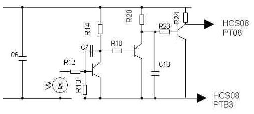
I tried to do the schematic diagram here
ftp://dreambox:remote@ftp.webzzanine.net/
Learning function with a dreambox remote
Moderator: Moderators
-
The Robman
- Site Owner
- Posts: 21887
- Joined: Fri Aug 01, 2003 9:37 am
- Location: Chicago, IL
- Contact:
This remote is a JP1.2 remote. We will be adding support for JP1.2 in the next month or so.
Rob
www.hifi-remote.com
Please don't PM me with remote questions, post them in the forums so all the experts can help!
www.hifi-remote.com
Please don't PM me with remote questions, post them in the forums so all the experts can help!
-
Capn Trips
- Expert
- Posts: 3989
- Joined: Fri Oct 03, 2003 6:56 am
If I read his post correctly, Thierry is asking about something more ambitious. This remote is NOT a learner, and he wants to know what hardware bits to add to MAKE it a learner, as apparently, the chip seemingly responds to the 975 learn command.
(although he may not NEED the learning capability once he can load an upgrade)
(although he may not NEED the learning capability once he can load an upgrade)
Beginners - Read this thread first
READ BEFORE POSTING or your post will be DELETED!
Remotes: OFA XSight Touch, AR XSight Touch
TVs: LG 65" Smart LED TV; Samsung QN850BF Series - 8K UHD Neo QLED LCD TV
RCVR: Onkyo TX-SR875; Integra DTR 40.3
DVD/VCR: Pioneer DV-400VK (multi-region DVD), Sony BDP-S350 (Blu-ray), Toshiba HD-A3 (HD-DVD), Panasonic AG-W1 (Multi-system VCR);
Laserdisc: Pioneer CLD-D704.
Amazon Firestick
tape deck: Pioneer CT 1380WR (double cassette deck)
(But I still have to get up for my beer)
Re: Learning function with a dreambox remote
I couldn't access either of the images listed there.
Since it's an HCS08, figuring out the missing components should be based on other HCS08 remotes.
Can you tell which connections are which on the HCS08 chip?
If you look at the keyboard wiring first, that can help you orient to the rest.
If it is the chip I think you mean, The keyboard sense signals should be pins 33, 34, 35, 36, 41, 42, 43 and maybe 44. The keyboard scan signals might be 12, 13, 14, 15, 20, 21, 22 and 23. Or maybe they are 16, 17, 18, 19, 37, 38, 39 and 40. The main signal (though a probably 100 Ohm resistor) to the transistor controling the IR LED should be pin 8 on the HCS08 chip.
Once you orient to all that, finding the place that learning support should be connected wouldn't be too hard.
I think the input to the chip from the learning section must be on pin 32, so if pin 32 is connected to a place where a transistor is apparently missing then the board is probably laid out for learning and just has components missing. Otherwise, you probably need both the components and something to mount them on.
Last edited by johnsfine on Tue May 23, 2006 3:01 pm, edited 1 time in total.
-
The Robman
- Site Owner
- Posts: 21887
- Joined: Fri Aug 01, 2003 9:37 am
- Location: Chicago, IL
- Contact:
I copied them to my server...

Rob
www.hifi-remote.com
Please don't PM me with remote questions, post them in the forums so all the experts can help!
www.hifi-remote.com
Please don't PM me with remote questions, post them in the forums so all the experts can help!
-
The Robman
- Site Owner
- Posts: 21887
- Joined: Fri Aug 01, 2003 9:37 am
- Location: Chicago, IL
- Contact:
The only HCS08 schematic that we have on file right now is for the URC-10820...
http://www.hifi-remote.com/forums/dload ... le_id=2926
http://www.hifi-remote.com/forums/dload ... le_id=2926
Rob
www.hifi-remote.com
Please don't PM me with remote questions, post them in the forums so all the experts can help!
www.hifi-remote.com
Please don't PM me with remote questions, post them in the forums so all the experts can help!
I guess I misunderstood.
Since you have the schematic of the learning section, what do you need?
Are those components all missing so you need values?
Are you sure about the bottom connection of C7? That doesn't look right. maybe it goes to the other side of R13?
In a JP1.2 remote with 2 AAA batteries, those three transistors are MMBT3904, C7 and C18 are 10pF, R12, R18 and R23 are 1K, R14, R20 and R24 are 10K, R13 is 1M.
-
Mark Pierson
- Expert
- Posts: 3018
- Joined: Sun Aug 03, 2003 12:13 am
- Location: Connecticut, USA
- Contact:
Re: Learning function with a dreambox remote
Did you try inputting a 3-digit EFC for the 994 key move? If so, the HCS08 JP1.2 remotes use 5-digit EFC's. You can try preceding the EFC with "00" (i.e. EFC "123" would be "00123").thierry69 wrote:Unfortunatly even if magic key blink twice with 994, magic code does not match
Mark
Yes thank It was what I wantedJohnsfine wrote:Since you have the schematic of the learning section, what do you need?
Are those components all missing so you need values?
Indeed I made an mistake you're correctJohnsfine wrote:Are you sure about the bottom connection of C7? That doesn't look right. maybe it goes to the other side of R13?
Cheer you are extraordinary. I will test this and I would keep you informedJohnsfine wrote: In a JP1.2 remote with 2 AAA batteries, those three transistors are MMBT3904, C7 and C18 are 10pF, R12, R18 and R23 are 1K, R14, R20 and R24 are 10K, R13 is 1M
I tested with 3 and 5 digits, the remote don't works. I think there is a bugMark Pierson wrote: Did you try inputting a 3-digit EFC for the 994 key move? If so, the HCS08 JP1.2 remotes use 5-digit EFC's. You can try preceding the EFC with "00" (i.e. EFC "123" would be "00123").
I forgot about C6, and I think you forgot about at least one resistor that should be missing if the learning section wasn't populated.
In a 2 battery design, main power is an unstable 3 volts (vs. the regulated 3.3 volts in the 4 battery design).
I think the power rail of the learning section (top line of your schematic) is isolated from an unstable 3 volt source by a 100 Ohm resistor that you don't show, but that is likely missing if C6 is missing.
C6 in the one I'm looking at is .1uF to make the power in the learning section more stable than the power in the rest of the design. I assume the learning amplifier would be touchy about power noise coming through R14.
-
mr_d_p_gumby
- Expert
- Posts: 1370
- Joined: Sun Aug 03, 2003 12:13 am
- Location: Newbury Park, CA
Actually, we also have the URC-8820 Schematic (which pre-dates the URC-10820 by about 11 months). It's probably my fault that Robman and others cannot find it since I have not listed it in the forum file section before; it's there now.The Robman wrote:The only HCS08 schematic that we have on file right now is for the URC-10820...
http://www.hifi-remote.com/forums/dload ... le_id=2926
Anyway, the relevance here is that the 8820 is a two-cell remote that uses the 100-ohm resistor John was referring to. The 10820 is a four-cell remote that uses a voltage regulator IC. Now that you have schematics of both types, you'll need to see which is closer to the remote you have.
Mike England
Thank's You Mike for this schematic, it is very similar of mine.
May be the software is similar. Does the 994 function works in the urc8820 ?
in my remote
long magic -> blink twice
994
If I press magic one again the function end
else
if I press two other key (example key 1 and key 2) the led blink twice
May be the software is similar. Does the 994 function works in the urc8820 ?
in my remote
long magic -> blink twice
994
If I press magic one again the function end
else
if I press two other key (example key 1 and key 2) the led blink twice
Yes.thierry69 wrote: Does the 994 function works in the urc8820 ?
Surprising. I assume that was a short press of magic, which should have given you a short blink and then the remote is ready for entry of the five digit EFC number.thierry69 wrote: in my remote
long magic -> blink twice
994
If I press magic one again the function end
Does the usual method for testing an advanced code work?
Short press of Magic
key in first four digits of EFC number
Aim remote
Press last digit of EFC number and hold while checking the effect on the device.
And I assume the KeyMove is then defined (if you use key2 in that device mode you get the function of key1).thierry69 wrote: if I press two other key (example key 1 and key 2) the led blink twice