|
JP1 Remotes
|
| View previous topic :: View next topic |
| Author |
Message |
Dilligaf
Joined: 05 Aug 2003
Posts: 79
Location: Michigan
|
 Posted: Tue Jun 26, 2012 7:17 pm Post subject: Posted: Tue Jun 26, 2012 7:17 pm Post subject: |
 |
|
| @Robman Did you miss the post where you can cut the connector down cavity 4 leaving a 1x3 and 1x2 connector? you can then super glue these together back to back and use the existing connector, as an added bonus you can put the missing cavity in the corner where pin 1 is so you know the orientation. |
|
| Back to top |
|
 |
Hamsterman
Joined: 05 Jul 2012
Posts: 22
|
| Posted: Thu Jul 05, 2012 8:43 pm Post subject: Minor problem with Digikey 6 pin header |
|
|
Long time lurker, first time poster...
I just ordered and built the USB JP1 programmer described here. So far so good...THANK YOU MR. TYLER!
However, I couldn't use the 6 pin header (digikey #609-2376-ND) with the crimp terminals on the TTL-232R-3V3 USB/serial cable. The terminals are too large to fit the smaller holes where the header plugs into the remote, and so the wires/contacts only insert halfway into the terminal. Some of the bare terminal sticks out of the header, and the retainer flap is still sticking out a little...
Once inserted into the remote, there is barely any contact with the remote, and I only once managed a successful connection.
I used Dilligaf's suggestion to cut the existing terminal in two and proceeded. That seems to work, although I'm still getting intermittent connection to the remote. After following the USB troubleshooting guide, the driver was working, was the latest FDDI driver (I manually installed before plugging it in), and jp1xtest worked. Without touching anything, RM-IR can now see the remote.
Hamsterman |
|
| Back to top |
|
|
cauer29
Joined: 03 Feb 2010
Posts: 236
|
| Posted: Thu Jul 05, 2012 9:23 pm Post subject: Re: Minor problem with Digikey 6 pin header |
|
|
| Hamsterman wrote: | Long time lurker, first time poster...
I just ordered and built the USB JP1 programmer described here. So far so good...THANK YOU MR. TYLER!
However, I couldn't use the 6 pin header (digikey #609-2376-ND) with the crimp terminals on the TTL-232R-3V3 USB/serial cable. The terminals are too large to fit the smaller holes where the header plugs into the remote, and so the wires/contacts only insert halfway into the terminal. Some of the bare terminal sticks out of the header, and the retainer flap is still sticking out a little...
Once inserted into the remote, there is barely any contact with the remote, and I only once managed a successful connection.
I used Dilligaf's suggestion to cut the existing terminal in two and proceeded. That seems to work, although I'm still getting intermittent connection to the remote. After following the USB troubleshooting guide, the driver was working, was the latest FDDI driver (I manually installed before plugging it in), and jp1xtest worked. Without touching anything, RM-IR can now see the remote.
Hamsterman |
A little clarification is needed here. The Digikey part number 609-2376-ND is a connector "housing", not a header. If I understand you correctly, replacing the word housing for your use of the word header, you removed the pins with wires attached from the original 1 x 6 connector housing and attempted to install them into Digikey part number 609-2376-ND housing and they don't fit.
I get that part, but:
"The terminals are too large to fit the smaller holes where the header plugs into the remote"
I can't figure out what is being described here. The terminals are too large to fit the smaller holes? Are you trying to say that the terminals cannot be inserted far enough into the housing to fully seat and have the retainer flap sit flat? Are you certain that you inserted the pins with the correct side facing the flap?
It is possible that FTDI have changed the connector thay they're using. I've purchased 20 of these cables some time ago and every one of them had a standard FCI compatible 1 x 6 connector on them. I didn't have any problem transferring the pins to a standard FCI 2 x 3 connector housing. I've since done most of the remaining cables to FCI 2 x 4 connector housings for a different application.
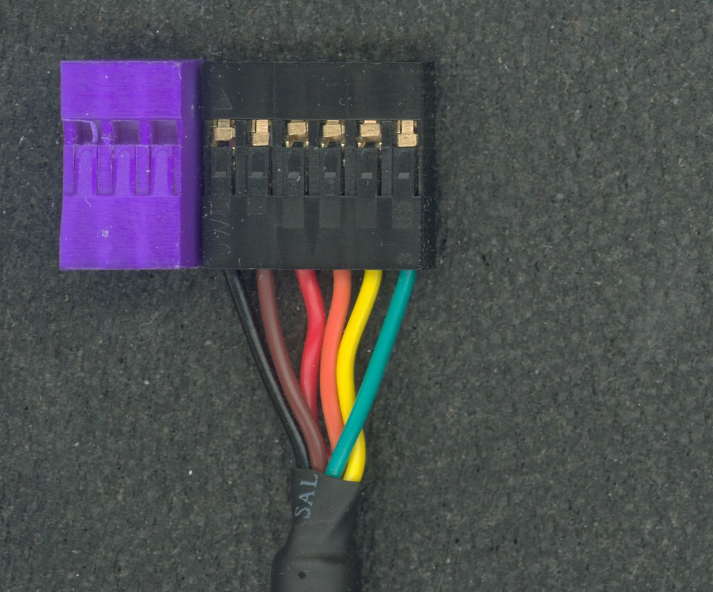
Look carefully at the Digikey connector housing and the 1 x 6 connector housing that came with the cable. Is the location of the retaining flaps the same with respect to the end of the housing that goes into the remote? Here's a picture of the 2 side by side:

As you can see, they line up perfectly.
A.A. |
|
| Back to top |
|
|
Hamsterman
Joined: 05 Jul 2012
Posts: 22
|
| Posted: Thu Jul 05, 2012 11:55 pm Post subject: Re: Minor problem with Digikey 6 pin header |
|
|
| cauer29 wrote: | | I can't figure out what is being described here. The terminals are too large to fit the smaller holes? Are you trying to say that the terminals cannot be inserted far enough into the housing to fully seat and have the retainer flap sit flat? Are you certain that you inserted the pins with the correct side facing the flap? |
Thank you for your response. You are correct in that the terminals do not go all the way into the Digikey header. The two headers do look very similar side by side, although the Digikey one is black as well. The terminals are silver in color and not copper as they appear in the photo.
If the terminal is inserted the wrong way, the retaining flap does not engage at all. But these terminals have two bumps, and the first one will not continue down into the header, and it seems to want to angle out of the header. I haven't cut off the red & brown pin so I went back to try inserting them into both headers. I had no trouble re-inserting them into the old header, and had the same problem with the Digikey header.
I suspect the inside of the header is different. I should note that the cable's header looks exactly the same, including the molded arrow for 'pin 1', so I'm at a loss as to what changed.
Hamsterman |
|
| Back to top |
|
|
cauer29
Joined: 03 Feb 2010
Posts: 236
|
| Posted: Fri Jul 06, 2012 9:24 am Post subject: Re: Minor problem with Digikey 6 pin header |
|
|
| Hamsterman wrote: | Thank you for your response. You are correct in that the terminals do not go all the way into the Digikey header. The two headers do look very similar side by side, although the Digikey one is black as well. The terminals are silver in color and not copper as they appear in the photo.
If the terminal is inserted the wrong way, the retaining flap does not engage at all. But these terminals have two bumps, and the first one will not continue down into the header, and it seems to want to angle out of the header. I haven't cut off the red & brown pin so I went back to try inserting them into both headers. I had no trouble re-inserting them into the old header, and had the same problem with the Digikey header.
I suspect the inside of the header is different. I should note that the cable's header looks exactly the same, including the molded arrow for 'pin 1', so I'm at a loss as to what changed. |
I will do some investigation to figure out exactly what happened and what needs to be done.
A.A. |
|
| Back to top |
|
|
Hamsterman
Joined: 05 Jul 2012
Posts: 22
|
| Posted: Fri Jul 06, 2012 5:15 pm Post subject: Re: Minor problem with Digikey 6 pin header |
|
|
| cauer29 wrote: | | I will do some investigation to figure out exactly what happened and what needs to be done. |
PM me if you want me to send you the Digikey header and the cut off wires from the cable for you to experiment with.
Hamsterman |
|
| Back to top |
|
|
cauer29
Joined: 03 Feb 2010
Posts: 236
|
| Posted: Fri Jul 06, 2012 6:31 pm Post subject: Re: Minor problem with Digikey 6 pin header |
|
|
| Hamsterman wrote: | | PM me if you want me to send you the Digikey header and the cut off wires from the cable for you to experiment with. |
Hold off for the moment. I have someone that just bought the same parts from Digikey and is going to bring them over tomorrow. If they have the same issue as yours, I'll be able to figure out what changed. If not, then I'll take you up on your offer.
A.A. |
|
| Back to top |
|
|
cauer29
Joined: 03 Feb 2010
Posts: 236
|
| Posted: Sat Jul 07, 2012 1:06 pm Post subject: Re: Minor problem with Digikey 6 pin header |
|
|
| cauer29 wrote: | | Hold off for the moment. I have someone that just bought the same parts from Digikey and is going to bring them over tomorrow. If they have the same issue as yours, I'll be able to figure out what changed. If not, then I'll take you up on your offer. |
Ok, it is confirmed. The FCI connector housing is the culprit. Examining the FCI housing next to one that works, it is extremely difficult to spot the difference. I managed to talk the local FCI rep out of some pin samples before I left work yesterday and when I compare those pins to the ones on the FTDI cable, the FCI pins are ever so slightly slimmer. That's why they're able to fit properly in the FCI housing. I'll post some pictures later today.
The bottom line is that the Digikey part number 609-2376-ND FCI connector housing, is not compatible with the FTDI cable pins.
I'll have to find a Digikey or Mouser part number for the proper connector housing. It's funny that when I look around my lab and search through the junk drawers for connectors, I find nothing but ones that ARE compatible with the FTDI cable pins.
A.A.
Ok, here are the pictures showing why the Digikey 609-2376-ND connector housing will not work with the pins from the FTDI cable:
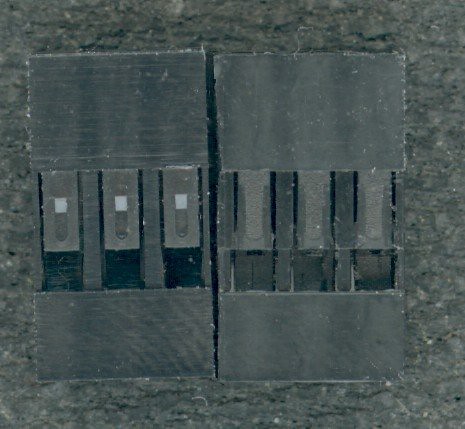
The picture above shows the Digikey 609-2376-ND connector housing next to one that I dug out of a drawer that fits the pins from the FTDI cable perfectly. The visible differences here are incosequential and offer no hint of why the FTDI cable pins don't fit the Digikey connector housing.
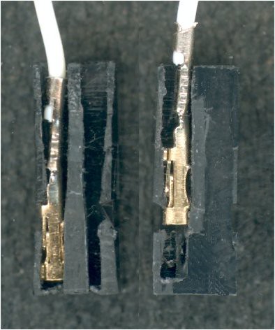
This cross-sectional picture shows that the Digikey FCI connector housing is much tighter inside and it's easy to see that the pins on the FTDI cable cannot be fully seated in the connector housing. The connector on the left from my junk drawer, has plenty of room for the pin to go all the way into the housing, while the one on the right gets hung up just past the flap. Even eliminating that hang up, you still can't get the pin all the way in, as there are a couple of nubs protruding from the side of the connector housing slot that prevent the pin from ever getting all the way to the front. The proper FCI pins are narrower and slightly shorter and so fit with no issue.
I believe that I have located an alternative compatible connector housing, but won't know for certain for a few days.
A.A. |
|
| Back to top |
|
|
Hamsterman
Joined: 05 Jul 2012
Posts: 22
|
| Posted: Sat Jul 07, 2012 10:52 pm Post subject: |
|
|
Thanks for the investigation, and good luck finding a new housing! I was afraid I was experiencing Operator Headspace Error.
I added a couple of 'durability enhancements' to the cable. First, I cut off part of a 'fat' paper clip and glued it into the 1 and 5 positions. This lets me insert and remove the cable from the remote without pulling on the wires. If you, like me, have a 'cut down' original housing, then you'll need something like a binder clip to hold the wire in place while the glue sets.
Second, I put a little hot melt glue into the wire/connector and wrapped it with tape up to the main cable. This should provide some additional support to the wires at their most vulnerable point.
Hamsterman
PS-I also painted Pin 1 with a little correction fluid on the housing and on the remote. |
|
| Back to top |
|
|
cauer29
Joined: 03 Feb 2010
Posts: 236
|
|
| Back to top |
|
|
The Robman
Site Owner
Joined: 01 Aug 2003
Posts: 21237
Location: Chicago, IL
|
| Posted: Thu Jul 12, 2012 7:50 pm Post subject: |
|
|
Tommy just updated the doc to use the Mouser parts instead.
_________________
Rob
www.hifi-remote.com
Please don't PM me with remote questions, post them in the forums so all the experts can help! |
|
| Back to top |
|
|
tranx
Joined: 13 May 2012
Posts: 682
Location: Hants, UK
|
| Posted: Fri Jul 27, 2012 8:49 am Post subject: Connectors and Trace Crimps |
|
|
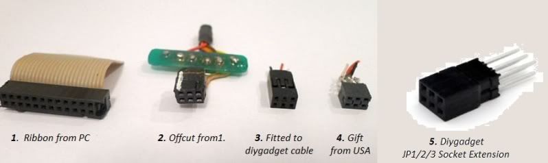
As a raw beginner I have been following this thread but by bad luck I started off a day or two after Tommy stopped offering cables! I bought a bare wire FTDI cable and did #1. and #2. three times but each example only lasted a short time before becoming unreliable due to the wires breaking or making tenuous contact within the cut down block.
Then I got a diygadget ready made cable and #3. with wires already crimped into the pins, but with much abuse soon broke a wire or two. Attempts to solder them back were untidy and the pins soon became distorted so they would not fit back, or kept slipping out again in use, or the wires broke off again.
I agree it is best to just buy the complete cable especially since the individual connectors seem not to be available in Uk without getting an industrial quantity to make the individual cost reasonable. However by then I already had two cables just needing connectors, while experience suggested that even the ready made kit was liable quickly to fail in my hands.
I was very kindly given a couple of connectors #4. with heat shrink to match. My first attempt at soldering these to the diygadget cable did not last long. The pins are slender and form part of the delicate metal pressing which slips into the housing and the diygadget wires are also very fine, which makes them form a micro-rat’s nest when they take the hot solder, so my best efforts were again untidy.
The second try seems to have succeeded and was achieved by using tiny copper tubes: Trace Crimps Black Copper 2 size 1.1mm (aka ‘rig crimps’ for fishing) to enclose the bare wire ends and the connector pins, and 2.4mm 1:3 ratio Heat Shrink Heatshrink Tube Sleeving Wrap to protect the vulnerable wire near the joint as well as the pins themselves.
Four of the tubes were cleaned out and ground to a length about 3mm longer than the connector pins or, in the case of fitting the diygadget extender plug #5 the pins were cut to a suitable length, to allow room for each wire.
With the connector inserted into a spare remote to hold things steady and keep everything in line, a tube was then soldered onto each of the four pins required on the diygadget socket extension.
With various diameters of heat shrink tubing, as follows, slid back down the wires, they could very easlily be soldered into the ends of the tubes.
Each wire carried a piece of 2.4mm heat shrink and after shrinking that in place they were collectively doubled back and secured with 1/4“ of wider heat shrink before the whole lot and the connector were finally enclosed in a sleeve of the wider heat shrink
The original bare wires FTDI cable was fitted in the same way to a JP1 extender from diygadget #5. in the picture, which I have been shown more recently. That has beefier wires so the 'trace crimps' made it even easier to do because they give more of a 'handle'. However the cable itself, being heavier, is not as convenient to use as the diygadget cable.
- and so far it is good.
Last edited by tranx on Mon Aug 13, 2012 11:50 am; edited 5 times in total |
|
| Back to top |
|
|
cauer29
Joined: 03 Feb 2010
Posts: 236
|
| Posted: Fri Jul 27, 2012 9:07 am Post subject: Re: Connectors and Trace Crimps |
|
|
It sounds like you could use some of the "hardware hackers secret weapon".......hot-melt glue. Sorry, I don't know what name it's called in the UK, probably something like "doffer's blue bland". Anyway, it's great stuff for securing wires that are prone to breakage from handling.
http://www.amazon.com/Stanley-GR20K-Trigger-Feed-Melt/dp/B000NIFKRM/
The glue remains slightly flexible after setting up. Applying this to secure the wires to the connector housing improves the overall durability greatly. You can put shrink tubing over it when done.
A.A. |
|
| Back to top |
|
|
tranx
Joined: 13 May 2012
Posts: 682
Location: Hants, UK
|
| Posted: Fri Jul 27, 2012 9:34 am Post subject: |
|
|
Thanks A.A.
That does look good.
Regards
Chris |
|
| Back to top |
|
|
dailyglen
Joined: 24 Nov 2009
Posts: 29
|
| Posted: Mon Aug 13, 2012 9:22 am Post subject: Would this cable also work? |
|
|
Hi,
I spotted this $9 USB to serial converter and was wondering if you think it would work:
https://www.dealextreme.com/p/usb-to-uart-5-pin-cp2102-module-serial-converter-81872?item=2
If so, in order to connect the cable correctly, what are the pinouts of the 6 pin connector for a JP1.3 remote? The other docs just say the color connections (AFAIK). The individual connectors could be super-glued together.
Thanks. |
|
| Back to top |
|
|
|
|
You cannot post new topics in this forum
You cannot reply to topics in this forum
You cannot edit your posts in this forum
You cannot delete your posts in this forum
You cannot vote in polls in this forum
|
Powered by phpBB © 2001, 2005 phpBB Group
|