
Is the Cox 8820BC0 a JP1.3 remote?
Is the Cox 8820BC0 a JP1.3 remote?
Has anyone seen on of these and can confirm if it's JP1-able? I really like the looks of it, and it's backlit, and only $12 shipped on ebay. HERE's the manual. They appear to be very similar to DirecTV remotes in that you hold MUTE+SELECT to program it instead of using a Setup button.
-
unclemiltie
- Expert
- Posts: 1819
- Joined: Wed Jan 21, 2004 12:50 pm
- Location: Pittsburgh, PA
-
unclemiltie
- Expert
- Posts: 1819
- Joined: Wed Jan 21, 2004 12:50 pm
- Location: Pittsburgh, PA
There were about six people selling this remote. I asked each one of them if they could check for me or send me a picture. So far, only one person has responded.mdavej wrote:Don't have one yet. Wanted to make sure it had pins first.
another one just answeredjhonyramona wrote:Hi there just look and there is No pin conectors
then he sent this response.00darkknight wrote:sorry but these are all brand new sealed remotes.
These are the latest models though not to worry
thnaks!
and now this response.00darkknight wrote:it has the reg battery style for 2 aa batterys there is no pins just coils
Could they have moved it to the bottom and made it a female connector? Or do you think those are just holes to vent the batteries, so they don't explode?


Remotes; JP1.2: Comcast URC-1067, JP1.3: Insignia NS-RC02U-10A, JP1.4 OARI06G, JP2.1: Cox URC-8820-MOTO (still trying to figure out how to make them self-aware.)
-
Kevin Timmerman
- Expert
- Posts: 142
- Joined: Tue Jan 09, 2007 5:52 pm
- Location: West Michigan
Great. Thanks to all for the info. I'll pull the trigger.
Eferz, who had the best price? Was it THIS guy selling 2 for $16?
Kevin, have you seen this before and do you know the pinout? Could it be JP1.4/JP2 or do you think it's just JP1.3?
Thanks
Eferz, who had the best price? Was it THIS guy selling 2 for $16?
Kevin, have you seen this before and do you know the pinout? Could it be JP1.4/JP2 or do you think it's just JP1.3?
Thanks
Yes, that seems like the best price so far. "$8 each" and free expedited shipping. He has 9 more lots left. I may even may even buy a pair.mdavej wrote:Eferz, who had the best price? Was it THIS guy selling 2 for $16?
Edit. Now they have 7 left.
You know when you're hesitant in doing something? And someone tell you to go get a pair? Yep, that's what I just did.
Btw... got this message too.
candi1232 wrote:It doesn't have it in the battery compartment but, it does have a five pin slot in the bottom of it.
Seems like it's for a data cable or something.
There is five little holes on the bottom of the remote.
Remotes; JP1.2: Comcast URC-1067, JP1.3: Insignia NS-RC02U-10A, JP1.4 OARI06G, JP2.1: Cox URC-8820-MOTO (still trying to figure out how to make them self-aware.)
OK, I received the remote and did some testing. It's JP2 or JP1.4, and I can read/write to it. Looking at eferz's pic of the connector, from top to bottom the pins are 1, 2, 3, 4, 6 if you connect them to the same on a JP1.3 cable. HERE's the RDF/Map/Image.
I tried to open the remote and look inside, but I couldn't get it to pop open. I think it's glued shut.
Because of the strange connector, I made myself a coupler with thick craft wire and hot glue. If anyone knows of a good permanent solution, please post it.
Findings so far, no learning, 995 macros or key moves possible via the key pad. However 978 device specific macro does work. And I like the blue backlight. One thing missing is a skip fwd button.
Last edited by mdavej on Mon Jan 16, 2012 10:26 pm, edited 6 times in total.
It's not held on by glue. There's just quite a bit of tabs you have pry open with spudgers. You'll have to use two because until three are unlatched they'll keep on relocking themselves. Unfortunately, I only have one nylon spudger and tried to use a precision screwdriver. Going to have to sand off the areas which was pried with the driver.mdavej wrote:I tried to open the remote and look inside, but I couldn't get it to pop open. I think it's glued shut.
I had it open last night and took the following photograph below. Didn't post it yet because I was waiting till daylight to get better shots. However, making the wiki page for the RemoteChart distracted me a little.

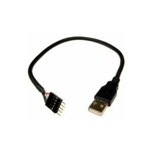
The connector isn't so strange. Looks like a single row 5 pin IDC connector. These are usually used by internal USB connectors like the one at the end of the cable pictured below. I'm going to go into Fry's later today and see if I can pick up some heat-shrink tubing along with a couple of wires and maybe a shroud. See what kind of Frankenstein cable I can come up with.mdavej wrote:Because of the strange connector, I made myself a coupler with thick craft wire and hot glue. If anyone knows of a good permanent solution, please post it.
Awesome! I'd like to play to. *smile* *wink* *wink*mdavej wrote:OK, I received the remote and did some testing. It's JP2 or JP1.4, and I can read/write to it. Looking at eferz's pic of the connector, from top to bottom the pins are 1, 2, 3, 4, 6 if you connect them to the same on a JP1.3 cable. I've started an RDF/Map/Image.
Remotes; JP1.2: Comcast URC-1067, JP1.3: Insignia NS-RC02U-10A, JP1.4 OARI06G, JP2.1: Cox URC-8820-MOTO (still trying to figure out how to make them self-aware.)
Okay, here's how I propose to physically connect it. All is necessary is a a 10 pin (2x5 IDC) Box Header a couple of wires, some solder, and heatshrink tubing.mdavej wrote:OK, I received the remote and did some testing. It's JP2 or JP1.4, and I can read/write to it. Looking at eferz's pic of the connector, from top to bottom the pins are 1, 2, 3, 4, 6 if you connect them to the same on a JP1.3 cable. I've started an RDF/Map/Image.
Because of the strange connector, I made myself a coupler with thick craft wire and hot glue. If anyone knows of a good permanent solution, please post it.

- Cut the bottom row of pins to allow the top row to be plugged into the back of the remote. The max depth of the socket is about 3/16th of an inch.
- Solder a wire to short the back of pin 4 so it shorts the front of other pin 4
- Connect the back of pin 6 to front of the other pin 5.
- Viola, you have yourself a 2x3 pin to single row 5 pin adapter.
Remotes; JP1.2: Comcast URC-1067, JP1.3: Insignia NS-RC02U-10A, JP1.4 OARI06G, JP2.1: Cox URC-8820-MOTO (still trying to figure out how to make them self-aware.)
Darn it. I was hoping that it wasn't going by the IDC conventions. Oh well, back to the drawing board. In the mean time, I'll leave you with naked pictures of my cox. Hope you all enjoy it.mdavej wrote:Great idea. Thanks. But it has to change a little. The pinout is actually 5 3 1 across the top and 6 4 2 across the bottom. I think it should work without pin 1 connected at all, but will have to confirm.


Btw, should we christian the connecter for this remote "JP2.1" as it is silk-screened on the PCB?


Remotes; JP1.2: Comcast URC-1067, JP1.3: Insignia NS-RC02U-10A, JP1.4 OARI06G, JP2.1: Cox URC-8820-MOTO (still trying to figure out how to make them self-aware.)
LOL. Thanks for the pix. I'm glad you were talking about your remote.
I suppose we should call it JP2.1, pending any significant differences we see between this and other JP2 remotes.
Here are a few more observations about the unique operation of this remote:
- No setup key, instead press Mute and Select simultaneously (like on a DirecTV remote)
- Long press of Power runs master power macro
- Long press a single number during device code entry to do a code search within a particular type/brand of device (detailed in manual)
- Device code search performed by holding Select until a code as found. When you device turns off, release Select to lock in the last code (2 blinks)
- Doesn't respond to learn, keymove or macro (995), but does do DSM (978)
- VPT isn't 993, but rather just Vol+ followed by punch thru device. This changes the VPT device for all devices. Vol- does nothing.
- Likewise Channel lock it Ch+ followed by lock device. Ch- does nothing.
- Holding PIP Swap and A for 2 blinks changes to one of the 3 cable setup codes, and PIP Swap and B changes to another.
-
Tommy Tyler
- Expert
- Posts: 411
- Joined: Sun Sep 21, 2003 11:48 am
- Location: Denver mountains
Stealing any ideas I could from eferz and mdavej, I have published an article HERE on how to build a 5-pin adapter for using a flash interface with a URC-8820 remote.
Tommy
Tommy